


The Sequence Diagram is one of the most interesting and useful diagrams in the Unified Modeling Language (UML).
It helps you document and understand the dynamic aspects of your software system - specifically the sequence of messages that are sent and received between objects. Sequence diagrams can help you comprehend and solve difficult issues in the process-intensive portions of your applications.
You often create a sequence diagram to model the logic of a use case.
This third article in the series covers one of the most interesting diagrams in the UML - the sequence diagram. They are most often used in the construction phase of software projects and are especially useful when analyzing the process-intensive portions of your application. Sequence diagrams are closely related to collaboration diagrams (discussed in the next article in this series). While the collaboration diagram's main focus is to show how objects are associated with each other, sequence diagrams show the time ordering of messages between objects.
Why use Sequence Diagrams?
As mentioned in the previous article on class diagrams, unless you are using business objects in your applications, you won't have much need for sequence diagrams. This is because if you're not using business objects, most of your application logic resides inside methods of user interface objects or in functions and procedures?and there really isn't much messaging that occurs between objects. However, once you decide to elevate your programming by using business objects in your applications, sequence diagrams help you answer two very important questions:
These questions are very difficult to answer correctly when you simply try to envision object messaging in your head. In contrast, when you document your thought process in a sequence diagram, suddenly the answers to these questions become crystal clear. At a higher level, it also helps you comprehend the overall flow of a particular process. In addition, sequence diagrams help you easily identify unnecessary messages between objects and factor them out. You may also discover that objects you originally thought should be involved in a particular process shouldn't be involved at all!
Modeling Use Cases
So, what kinds of things should you document in a sequence diagram? Usually, a sequence diagram is used to document the logic of a use case (for a discussion of use cases, see Component Developer Magazine, Issue 2 - 2001).
In this article, we'll go step-by-step through the process of building a sequence diagram for a particular use case, but first, you need to learn about the different elements of sequence diagrams.
Sequence Diagram Elements
There are four primary elements of a sequence diagram:
- Objects
- Lifelines
- Messages
- Focus of control
Figure 1 demonstrates the use of each of these elements in a simple sequence diagram.
Objects
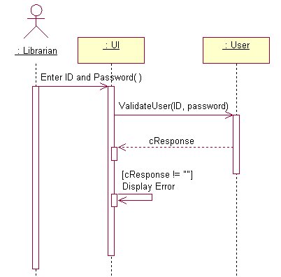
Objects that are involved in the sequence of events you are documenting should be placed at the top of the sequence diagram across its horizontal axis. As shown in Figure 1, it's a good idea to place the actor that initiates a particular sequence at the upper left side of the diagram. You can also place a “UI” (user interface) placeholder class on the diagram with which the actor interacts. This is an excellent tool for providing context for a use case.
Next, you can place objects on the diagram that are instantiated by the UI or by other objects. You should place the most important objects to the left and subordinate objects to the right. It's best to place objects on the diagram in a way that minimizes lines that cross.
Lifelines
The lifeline is the dotted line that extends down the vertical axis from the base of each object. The lifeline indicates the life span of an object over a period of time.
Messages
Messages are the most important elements of a sequence diagram. They indicate when one object calls an operation on another object (or itself). They are also used to indicate return values. Message flow begins at the top left object (which is usually an actor) and flows down the vertical axis from one object to another.
Messages are shown on UML diagrams as labeled arrows, with the arrowhead indicating the direction of the call. When a message is sent to an object, the text associated with the message specifies the name of the method that is being called on the receiving object. For example, in Figure 1, the ValidateUser() message is sent to the User object. This indicates that the User object has a method named ValidateUser. In addition, the ValidateUser() method accepts two arguments: ID and password. With most modeling tools you can optionally display the type of the arguments (e.g., boolean, currency, string).
When a message is sent from an actor to the user interface, it does not indicate the name of a method on the UI. Rather, since the UI class is simply a placeholder, the message text is used to indicate the action that the actor performs (e.g., “Enter ID and password”).
Note: When you add a message to a sequence diagram, most modeling tools automatically add a corresponding operation to the class that receives the message.
When an object calls an operation on itself, this is known as a reflexive message or message to self. For example, in Figure 1, the UI object (though not a real object) has a reflexive “Display error” message.
It is not necessary to document a return for every message on a sequence diagram, because in the UML specification a return is implied. However, if the method is returning something of interest, it's perfectly valid to show the return value on the diagram.
Focus of Control
Focus of control (FOC) is used in sequence diagrams to show the period of time during which an object performs an action. FOC is rendered as a thin, rectangular object that sits on top of object lifelines. The top of the FOC rectangle coincides with the receipt of a message. The bottom of the rectangle coincides with the completion of an action and can be marked with a return message.
FOC rectangles can be stacked in layers on a sequence diagram to indicate focus of control nesting. This layering usually occurs when an object makes a call to self (Figure 1) or receives a callback from another object.
Creation and Deletion of Objects
The vertical position of an object in a sequence diagram indicates when it is instantiated. If an object is “alive” from the beginning of the entire sequence, you should place it at the top of the diagram and its lifelines should extend to the bottom. If an object is instantiated at a later time, you should move it down the vertical axis to the place at which it is instantiated. If an object is destroyed before the end of a sequence, you can indicate this by placing an “X” at the bottom of the lifeline at the point where the object is released.
Specifying Recurrence
At times, you need to indicate that a particular message is run conditionally, or you may want to specify its iteration (how many times it is called). Both of these adornments fall into the category of recurrence. In the UML, you can indicate recurrence by placing text in square brackets above a particular message.
Sequence diagrams can help answer the question, “Which objects should be assigned a particular responsibility?”
For example, in Figure 1, the “Display Error” message is called conditionally. The text in square brackets above the message indicates that “Display Error” is only called if the cResponse string returned from the ValidateUser() operation is not empty.
Creating a Sequence Diagram
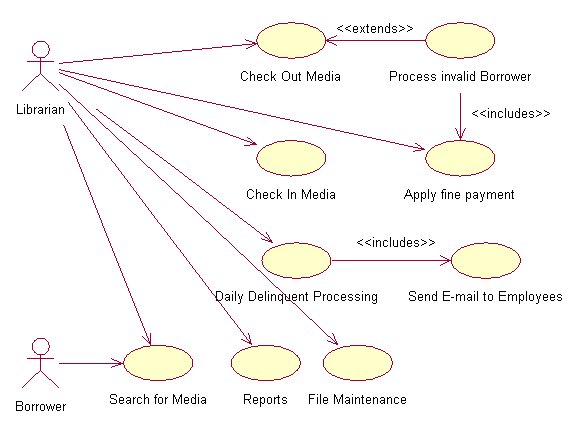
As mentioned previously, you often create a sequence diagram to model the logic of a use case. To demonstrate the correlation between use cases and sequence diagrams, let's use a software system for a company's in-house technical library as an example. There are a variety of use cases shown in Figure 2 for our simple library application - checking out media, checking in media, searching for media, and so forth. You can create a sequence diagram for each of these use cases.
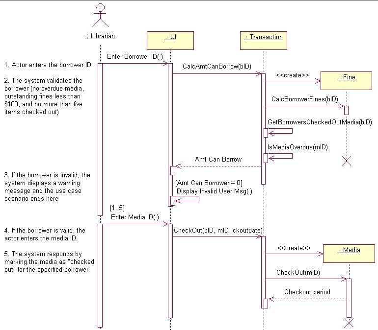
The “Check out media” use case is a good one to use as an example. The finished sequence diagram for this use case is shown in Figure 3. The following steps show how this diagram was created.
Step 1: Select a Use Case
We've already decided that we are going to model the “Check out media.” Here is the flow of events description for the use case:
Step 2: Add the Actor, UI Objects and Use Case Text
Each use case is carried out by an actor (signifying a specific type of user). This step simply involves adding the appropriate actor and a UI class to the sequence diagram, as shown in Figure 3.
You can create a single UI placeholder class to represent all interaction with the user interface, or you can create a different class for each user interface element in your application (for example, a different UI class for each user entry form). In either case, the appropriate user interface class needs to be added to the sequence diagram.
After adding the actor and UI object to the diagram, add a message between the actor and the user interface that indicates the action taken by the user. In our example in Figure 3, an “Enter Borrower ID” message is added from the actor to the UI object.
Although it's not imperative, you can add the text of the use case to the sequence diagram. This can go a long way towards helping others understand your diagram. It provides a simple, human language representation of what the sequence diagram is accomplishing. If you decide to add use case text to your sequence diagram, add it in the left margin of the diagram as shown in Figure 3.
Step 3: Select Classes to Carry out the System Response
When choosing the classes that carry out the system response, you need to examine each step of the use case and add the appropriate classes to the diagram. This may take a bit of thought, because it may not be readily apparent which class you should choose to carry out each responsibility.
In our example, the Transaction and Fine objects have been selected to carry out step 2 of the use case.
Step 4: Add Messages Between Objects
This step involves adding messages between objects to carry out each step of the use case. This includes both message calls and, optionally, return values.
In our example (Figure 3), a CalcAmtCanBorrow() message is sent from the user interface to the Transaction object along with the borrower ID (bID) argument. As specified in step 2 of the use case, there are three criteria the borrower must pass in order to check out media. Since the Transaction object keeps a log of all check-in and check-out transactions for each borrower, it can determine by checking the transaction log if 1) the specified borrower has any overdue media, or 2) has less than five items checked out.
However, in order to determine if the borrower's fines are less than $100, the Transaction object needs to instantiate the Fine object and send it a CalcBorrowersFine() message. This happens behind the scenes (without the knowledge of the user interface), because the instantiation, calling and release of the Fine object is encapsulated within the Transaction object's CalcAmtCanBorrow() method.
After receiving the outstanding fine amount from the Fine object, the CalcAmtCanBorrow() method performs its calculations and returns the number of media that the borrower is allowed to check out. Step 3 of the use case specifies that if the amount is zero, the system displays a warning to the user and the scenario ends there.
Step 4 of the use case specifies that if the borrower is valid, the actor enters the media ID. An “Enter Media ID” message is added between the actor and UI object to indicate this action by the user.
Step 5 of the use case says that the system responds by marking the media as “checked out.” The Transaction object and Media object have been chosen to carry out this action. A CheckOut() message is sent to the Transaction object, along with Borrower ID, Media ID and Date arguments. The Transaction object instantiates the Media object and sends it a CheckOut() message (including a media ID argument). The Media object marks the specified media as “checked out.” The Media object then returns the Checkout period - the number of days the specified piece of media can be checked out. Next, the Transaction object adds a record to the transaction log indicating the borrower, media, the date on which the item was checked out and due date (calculated from the checkout period). This completes the “Check Out Media” use case.
An additional item of note: The CheckOut() message has a recurrence of `[1..5]`` associated with it. This indicates that the message can be called 1 through 5 times based on the number of items the borrower is allowed to check out.
Using Color and Notes to Clarify Sequence Diagrams
At times when there are many “calls to self” and subsequent calls to other objects in a sequence diagram, you can end up with several FOC layers. You can help your diagram be more understandable by choosing a different fill color for each FOC layer. This makes it much easier to identify the methods and objects that have focus at any given time.
You can also use notes to your advantage to help clarify your sequence diagrams. For example, if a section of a diagram is particularly thorny or difficult to understand, simply attach a note to one of the methods adding text to clear up any confusion.
Summary
Sequence diagrams are an excellent tool for modeling the dynamic aspects of your system. They help you see the big picture of message flow between objects that carry out the logic of use cases. With a little practice, sequence diagrams can help you build more streamlined and bug-free interactions between objects in your software applications.