


The Visual Studio SDK contains tools that make it easy to define and implement graphical Domain-Specific Languages (DSLs) and associated code generators in Visual Studio.
The term domain-specific development refers to an approach to software development involving the use of DSLs to drive code generators. The tools contained in the Visual Studio SDK are collectively called the “DSL Tools” and use domain-specific development techniques to create and implement DSLs for use in Visual Studio. This article illustrates the domain-specific development approach through an example, and then shows how you can use the DSL Tools in the Visual Studio SDK to build the DSL used in that example.
Domain-Specific Development
The approach the authors call domain-specific development is a pattern of model-driven software development. It’s a very useful way of developing software when you’re building a specific type of solution; that is, when you’re building a solution in a particular domain. A domain could be a vertical one such as insurance underwriting systems, a horizontal one such as three-tier distributed applications, or a combination of the two such as retail shop-floor mobile applications. Figure 1 illustrates the pattern.
The diagram shows the pattern having two main parts: a fixed part, embodied by a framework and a variable part, embodied by a model.
The fact that you’re building software in a specific domain implies that some elements of the solutions you might build in that domain are the same from one system to another. As has been good practice now for many years, to enable you to build systems in the domain more easily, you should capture those common elements in a reusable domain framework.
However, frameworks are often complex. To make using them easier, domain-specific development introduces a model of the part of the solution that is different from one application in the domain to another, for example, the specific UI, business, and data components that you need to create a retail banking three-tier application, as opposed to those components you need for a lending library management three-tier application. The elements that you’ll find in these models encapsulate the right patterns for using the framework. For example, an Entity element in the data tier of the model contains enough information to specify how to derive a class from some EntityBase class in the framework to form part of a data-access layer.
You can see that these models contain information that’s very specific to the domain-the information you’d find in them naturally represents the things you think about when building a solution in that domain. To accomplish this, you create domain-specific languages (DSLs) to represent them rather than using generic modeling languages. Figure 2 presents an example model in a DSL for representing the static structure of a three-tier application.
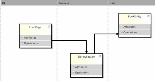
This DSL has three vertical swimlanes representing the three tiers of the application architecture. The elements in each swimlane represent the types of object you’d expect to find in each tier-each somewhat like a class with attributes and operations, but each distinct with their own specific properties, a page in the UI tier, a service façade in the business tier, and an entity in the data tier.
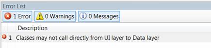
A key value of DSLs is that because they are specific to a problem, you can encode business and architectural rules about that problem into the modeling tool itself. For example, in the three-tier DSL, dependencies directly from the UI tier to the Data tier will cause the tool to display errors (Figure 3).
Going back to the pattern, you’ll see the framework has two inserts: a generated part and a handwritten part. The generated part is the integration between the fixed and variable parts of the solution. Typically a code generator runs across the model and produces code that extends the framework according to well-known patterns. For example, each Page element in the UI tier causes the code generator to generate a page in the solution, derived from an ASP.NET Page object. You might specify the master page to use for the page directly in the DSL or you might choose a more abstract representation and just provide a selection of common page types.
The final piece of the solution in a domain-specific development solution is the handwritten part. This acknowledges that in most cases neither the framework nor the model will capture everything that is needed to produce a 100% complete solution. There will usually be some solution-specific code that you are introducing for the first time in a particular solution. It’s generally accepted that harvesting code for reuse should wait until it’s been used at least a couple of times to prove its utility and this is equally so in the case of being able to establish the model that you need to generate from to parameterize it.
Some things are also simply better expressed in ordinary code than in modeling languages. For example, in this case, the logic and math to calculate the fine for an overdue book would be very clumsy to represent graphically, whereas you can express it clearly in code.
Realizing DSLs in Visual Studio
Now that you’ve seen how useful DSLs can be in domain-specific development, this article will show you what kind of extension to Visual Studio you’ll need to build to have a DSL modeling tool in your IDE.
Figure 4 shows the main components of a DSL designer.
The key element here is the central graphical editor, which reads and writes a DSL as an XML file on disk. Because this editor is a document editing experience and you cannot add document editors using VSX add-ins, you must use a VSX package to build a DSL tool. Additionally, you must implement the diagram rendering, mouse gesture handling, and selection behavior.
The model explorer is a custom tool window with a hierarchical view of the whole model. You populate the Properties window by publishing the diagram or explorer selection to the IDE and providing a set of .NET property descriptors for the selected elements.
The toolbox entries are mini-chunks of serialized model data. You must provide them to the IDE and relate them to the DSL editor so they appear only when a user selects that window.
When a model is invalid, you must publish errors and warnings to the Error List window.
Less visually, you must make custom commands available in the IDE as toolbar, menu, and context menu entries, both for the editor window and the model explorer.
Figure 5 shows an outline of how the pieces of VSX package implementing a DSL fit together.
Finally, you must create code generation templates to generate your solution from your model on top of your domain framework; you must integrate these into the project system so the editor builds the generated code as part of the solution. By default, you do this using the SingleFileGenerator mechanism.
DSL Tools: Tools to Build Tools
This article has described what a DSL does and how you might use it to drive code generation on top of a framework. You’ve seen how you can realize a DSL as a Visual Studio extension; anyone who’s used the Visual Studio SDK knows that to do all this by hand would be a significant amount of work. Fortunately, Microsoft has created the DSL Tools which ship in the Visual Studio SDK and which greatly simplify the job of creating a DSL in Visual Studio.
The DSL Tools team at Microsoft has eaten a large bowl of its own dog food. In building the DSL Tools, the team applied the domain-specific development pattern to the job of creating a DSL itself.
In DSL Tools, you’ll find a set of frameworks to make it easier to create a DSL inside Visual Studio. You then use a graphical editor to build a model of the variable part-in this case what your individual DSL looks and behaves like. This model is called the DSL definition. Finally DSL Tools provides code generators which use the data in your DSL definition model to create a fully working implementation of a DSL on top of the frameworks.
Additionally, to get all of this set up to build in a Visual Studio project and to deploy it when finished, Microsoft provides two additional tools:
- The Domain-Specific Designer project template, which creates a pre-configured Visual Studio solution for authoring a DSL.
- The DSL Setup project template, which creates a pre-configured setup project which generates an MSI to install a DSL and its associated components.
The authoring process begins by running the domain-specific designer project template. This brings up a custom wizard asking for information like the name of the DSL and the namespace to be used for the code. The wizard creates a solution, called the authoring solution. Pressing F5 builds the code and brings up the experimental version of Visual Studio in which you can see a basic DSL working.
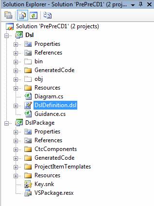
In the authoring solution (Figure 6), there is a file called DslDefinition.dsl, which defines the DSL. The code generation templates generate the code implementing the DSL from this definition into the generated code folders of the Dsl and DslPackage projects.
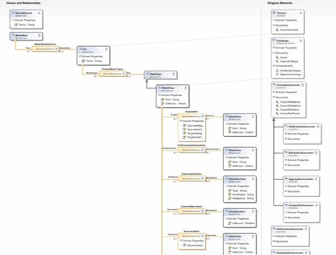
To change the behavior of the designer, you must edit the DSL definition file and then regenerate the code. You edit the DSL definition through the DSL Designer, which is itself a graphical designer built using DSL Tools. Figure 7 provides a high-level view of the DSL definition. On the left is the definition of the domain model and, on the right, the definition of the diagram elements used in the graphical notation for the DSL.
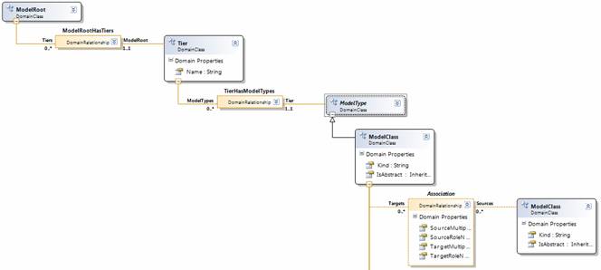
The domain model defines the concepts of the language ignoring how those concepts are represented notationally. DSL Tools expresses the domain model using classes and relationships. Figure 8 shows a core fragment for the domain model for the three-tier example, introducing the classes of ModelRoot, Tier, ModelType, and ModelClass (which specializes ModelType). It also defines a number of relationships: ModelRootHasTiers, capturing the notion that a class model contains a collection of tiers; TierHasModelTypes, capturing the notion that a Tier contains a collection of model type elements (some of which can be model classes); and Association, capturing the notion that a model class may be related to other model classes through an association.
The code that the generation templates generate from the domain model is a set of .NET classes, one for each class and relationship. The code manages the creation, update, and query of model elements (instances of domain classes) and links (instances of domain relationships) and is implemented on top of a framework which includes support for transactions, events, and undo. The generated classes provide strongly-typed access to model elements and links-for use in the development of code generators and other automation tools.
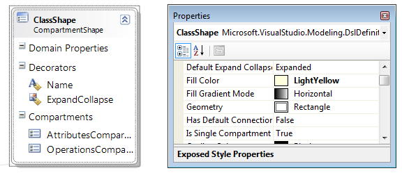
The diagram elements define the look and feel of the graphical notation used to represent the underlying concepts. For example, Figure 9 shows the definition of the shape used to represent a model class. ClassShape defines a rectangular compartment shape (Geometry is set to be rectangle), which means it can have compartments containing lists of elements. It has two compartments: one to list the attributes of the class and one to list the operations. It also has a text decorator, centered at the top of the shape, for displaying the name of the class.
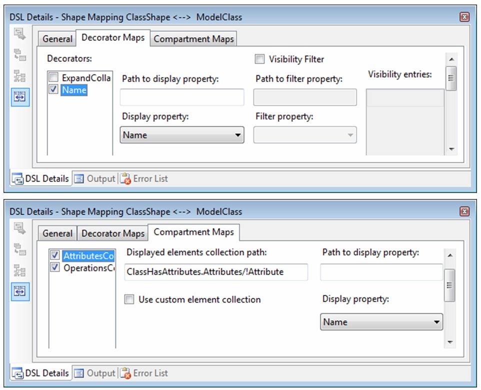
In order to visualize a domain model, you must map diagram elements to the domain model elements they represent, which is achieved through diagram element maps. Figure 10 shows some of the details of the map between ModelClass and ClassShape. The top image shows the mapping of the text decorator in the shape to the Name property of ModelClass, indicating that the decorator should always display the value of the property. The bottom image shows the mapping of the Attributes compartment, indicating the list of elements that the compartment should show (the attributes belonging to the class) and the string which should be displayed for each entry (which is the value of the property Name).
You can define many other types of diagram elements using a similar scheme, including connectors, image shapes, port shapes, and swimlanes.
The domain model and graphical notation define the concepts of the language and the way those concepts get presented through a graphical notation, but they don’t define everything required to get a fully working graphical designer. In addition, the DSL definition contains the following components:
- A definition of the toolbox, specifically element and connection tools for creating new model elements through the design surface.
- A definition of merge directives and connection builders, which define how newly created elements of particular domain classes are merged into an existing structure of elements and how connections between elements are created, where a connection can be something more sophisticated than just a single link.
- A definition of the behavior of the model explorer, specifically which nodes are visible, whether they have icons associated with them, and so on.
So DSL Tools have provided a design experience for implementing a graphical DSL in Visual Studio by generating code from a rich DSL definition. This is great and will allow you to build useful designers to drive domain-specific development. For more sophisticated DSLs, it’s likely you’ll want more control over the behavior of the designer than you can achieve through the DSL definition. It’s very important to make sure that in any development involving code generation from models that it’s always possible to dive into custom code when you reach the boundaries of what can be defined in the model. For this reason, the DSL Tools team was careful to design the code generators so that you can further customize the code that results, for example using partial classes. The team even added some flags to the DSL definition, which direct the generators to output a different shape of code to allow you to insert custom code.
When you’ve completed defining and implementing your DSL, you’ll want to deploy it. The third component of the DSL Tools is the DSL setup template, which allows you to add a setup project to the authoring solution for creating an MSI to install the designer. This is also model driven: there is a model (this time you edit it directly through XML) which lists the components to be installed (VsPackage implementing the DSL, supporting DLLs, item and project templates, and supporting files) and which generates WiX, which you then build to generate an MSI. To change what’s installed, you just go to the setup model, edit it, regenerate the WiX, and rebuild.
Further Resources
DSL Tools comes as part of the Visual Studio SDK. Microsoft sponsors a Web site dedicated to DSL Tools at http://msdn.microsoft.com/vstudio/dsltools">http://msdn.microsoft.com/vstudio/dsltools. This has links to a dedicated forum, as well as the authors’ blogs. Gareth Jones and Stuart Kent have also written a book on domain-specific development with Steve Cook and Alan Cameron Wills. For details see www.domainspecificdevelopment.com. The central part of the book is an in-depth dive into DSL Tools.
Gareth Jones is a software architect in the Visual Studio Ecosystem team at Microsoft. For the last four years he's been working on DSL Tools and software factories and now he's broadening those techniques to help make extending Visual Studio with any of your own tools a much easier, more accessible proposition. He co-authored the book, Domain-Specific Development with Visual Studio DSL Tools with other members of the DSL Tools Team. Previously at Microsoft he has been a development manager for bespoke enterprise solutions, led the development of Microsoft's bCentral UK business portal and managed a consultancy team focused on ISVs. Before joining Microsoft, Gareth led developments in the intelligence analysis, simulation, and aerospace industries.
Stuart Kent joined Microsoft in 2003 to work on tools and technologies for visual modeling, which culminated in the Domain-Specific Language Tools, which are now part of the Visual Studio core tooling platform and are described in a recent book (Domain-Specific Development with Visual Studio DSL Tools) that he co-authored. Stuart is now a Senior Program Manager with the Visual Studio Ecosystem team and is responsible for driving the development of tools to make it much easier to create extensions for Visual Studio-tools to build tools, as well as the continued evolution of DSL Tools. Before joining Microsoft, he was an academic and consultant with a reputation in modeling and model-driven development. He has over 50 publications to his name and made significant contributions to the UML 2.0 and MOF 2.0 specifications. He is a member of the editorial board of the Software and Systems Modeling journal, and on the steering committee for the MoDELS series of conferences. He has a PhD in Computing from Imperial College, London.
